Nizar Yousri
Infrastructure | DevOps | Automation Engineer

Lab / Playground

Motorcycle Keyless Start System (More to Come)

Replacing ignition keys with MQTT-based control and GSM geofencing

Overview

This project started as a personal challenge: could I replace the traditional motorcycle key with something smarter, something I could automate, monitor, and extend later?

The result became a full keyless ignition system built around an ATmega328P microcontroller using MQTT as the main control method. Instead of a physical key, the bike responds to MQTT topics—start, stop, fuel pump, lights—handled through lightweight messages on the network.

The SIM800L module is included for geofencing. It reports the location and notifies me if the bike moves outside a defined boundary.

Hardware Used

  • ATmega328P-PU microcontroller
  • SIM800L GSM module (location + geofencing alerts)
  • IRFZ44N MOSFETs (x3) for high-current loads
  • Flyback diodes (1N5408)
  • 220Ω gate resistors, 10kΩ pull-downs
  • LM2596 buck converter (12V → 5V)
  • 12V motorcycle battery
  • Terminal blocks and wiring

Features

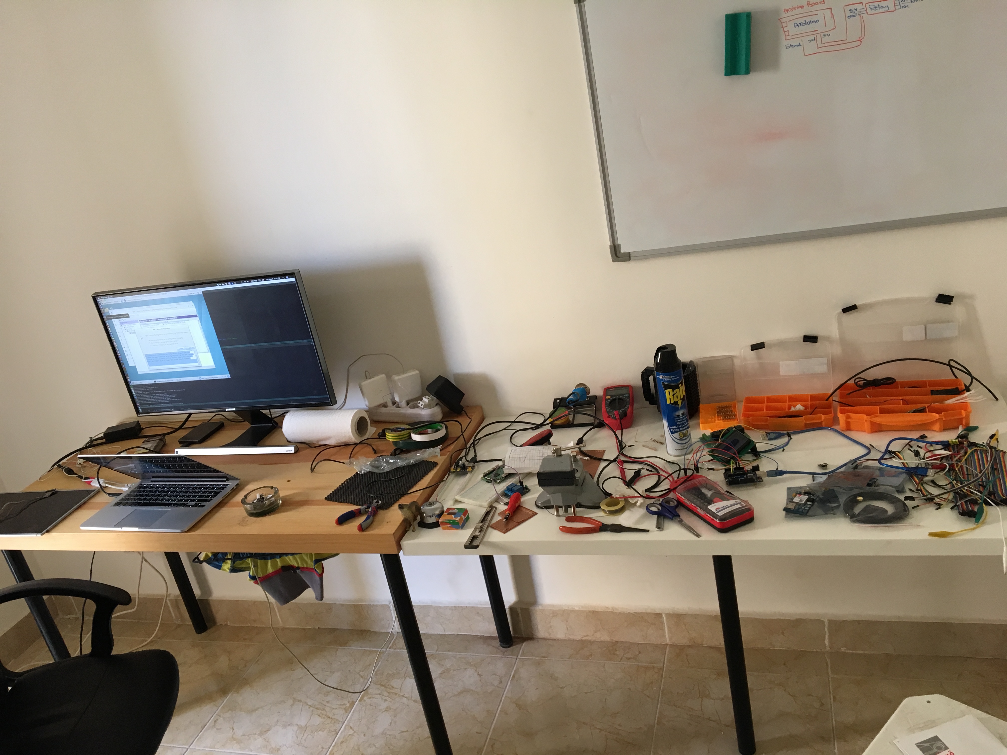
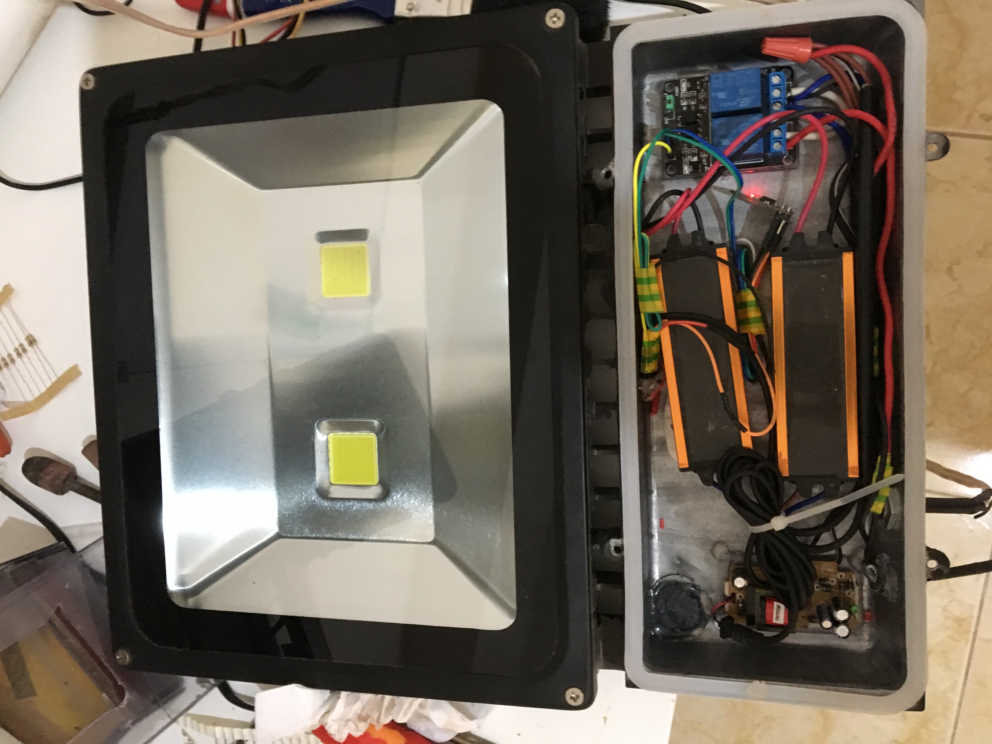
  • Start/stop motorcycle via MQTT messages
  • Remote control of fuel pump and main lights
  • MOSFET-based switching instead of mechanical relays
  • Geofencing alerts via SIM800L
  • Built with future mobile or cloud integration in mind

How It Works

The system maintains an MQTT connection over a small WiFi module attached to the ATmega. When a message such as bike/start or bike/lights/on is received, the microcontroller executes the corresponding action:

  1. Power the fuel pump
  2. Run the starter motor for a few seconds
  3. Handle light and auxiliary commands

Meanwhile, the SIM800L periodically sends GPS coordinates and raises an alert if the bike crosses a pre-set radius.

All high-current paths run through MOSFET stages for safety and fast switching.

Wiring & Installation

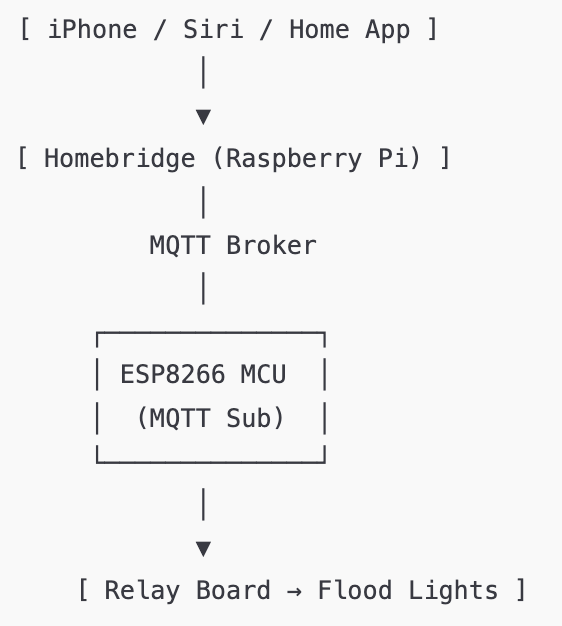
After finishing the electronics and firmware, I spent a good amount of time on the physical wiring.
I followed the motorcycle’s service manual closely, running the low-voltage control wires alongside the original harness and routing everything through the handlebars the same way the factory wiring is done.

The goal was to make the system feel native — nothing loose, nothing improvised.
Every cable was sleeved, heat-shrunk, and tied into place so the final result looks and behaves like part of the original motorcycle wiring loom.

Schematic

Yamaha Raider's Ignition circuitry

Next Steps

  • Move from breadboard to a custom PCB
  • Add RFID/NFC as a fallback authentication method
  • Build a mobile UI for MQTT control
  • Add battery/system health monitoring

Status

A working prototype is already in place, physically - Need to work more on the code though!

Images

A great example when the sun ruined the pose :D

Clips

I definitely should've used a pair of tweezers or pliers trying to grab a hold of this lead
Almost done with the wiring...
Just a time-lapse of fraction of what was done this day.

Smart Flood Light Automation using MQTT and Apple HomeKit

This project demonstrates a custom-built IoT home automation prototype that allows flood lights to be controlled using Apple’s Home App and Siri voice commands, powered by an ESP8266 Wi-Fi module communicating through an MQTT broker running on a Raspberry Pi.

Overview

This project began as a simple idea: I wanted to control a pair of outdoor flood lights through Apple’s Home App and Siri, using hardware I already had. With an ESP8266 and a Raspberry Pi running an MQTT broker, the whole setup came together quickly and turned into a reliable little smart-home prototype.

The goal was to show how inexpensive hardware can smoothly integrate with modern smart-home platforms, without losing performance or reliability.

Hardware Components

  • ESP8266 (ESP-01) as an MQTT client
  • 2-channel relay board for switching AC flood lights
  • Raspberry Pi hosting the Mosquitto MQTT broker
  • 5V power module for both ESP8266 and relay circuitry

Software Stack

  • Arduino C / AT commands to configure the ESP8266 and MQTT subscriptions
  • MQTT protocol for device communication
  • Homebridge + Apple HomeKit for integration with iOS and Siri
  • mosquitto_pub / mosquitto_sub for live debugging and message monitoring

How It Works

The ESP8266 subscribes to a specific MQTT topic.
When Homebridge publishes a message like "on" or "off", the ESP8266 toggles its GPIO pins accordingly, activating or deactivating the relay outputs that control the flood lights.

The result is a smooth, near-instant response: Siri sends the command, Homebridge publishes the MQTT payload, and the lights switch immediately.

Demonstration

  • Voice control using Siri to toggle the backyard flood lights
  • Terminal footage from the Raspberry Pi showing live MQTT messages being published and received

Next Steps

  • Move the setup to a custom PCB
  • Add current/voltage monitoring
  • Integrate more outdoor sensors and lighting zones
  • Add secure remote access through VPN or MQTT over TLS

Status

Fully working prototype, stable in daily use.

Images

Just an overview of the prototype
Exactly how it looks when I am in the mood for IoT
The heart of it all
The heart of it all

Clips

Please don't judge my slurry accent !